Wall-GapS™
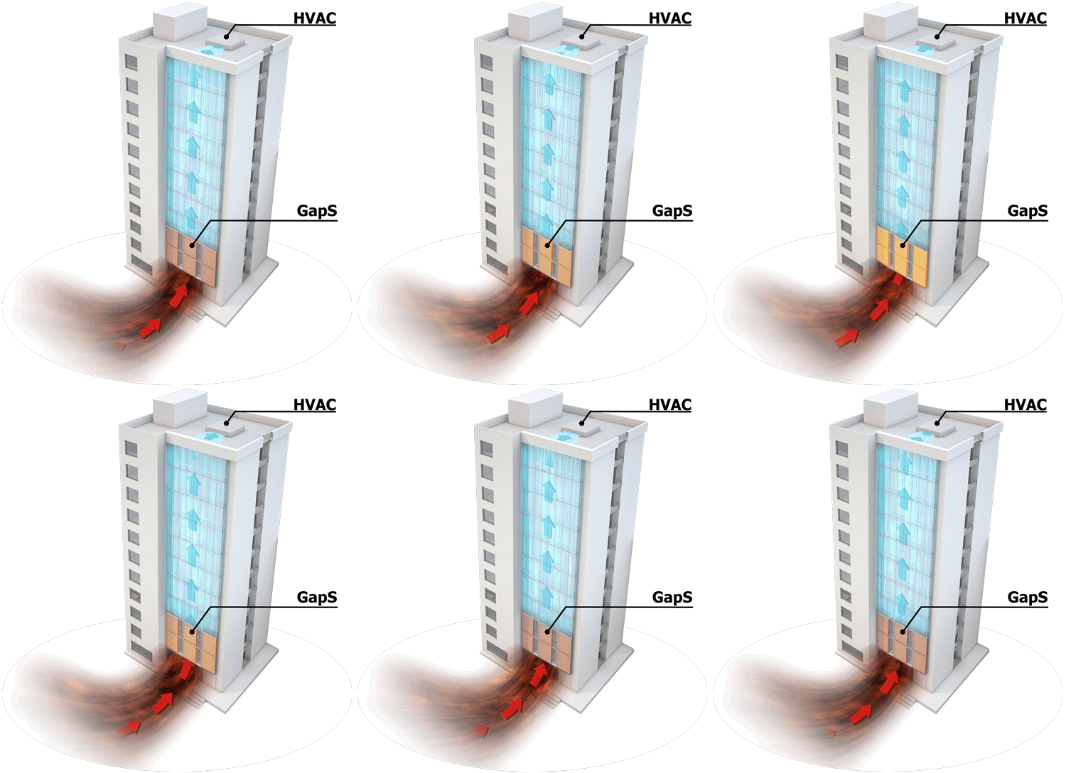
A patented, multi-functional exterior facade that replaces traditional building panels. It cleans and cools the outside air on its way into the building. The facade has no fans of its own; the building's existing air handlers draw the air through it. It also adds insulation, helping buildings save energy and improve air quality with benefits such as:
- Extra Insulations
- Clean Air
- IoT Smart Monitoring
- Colder Air Delivery
- Saving Energy
Data centre integration
Wall-GapS™ integrated in a data centre
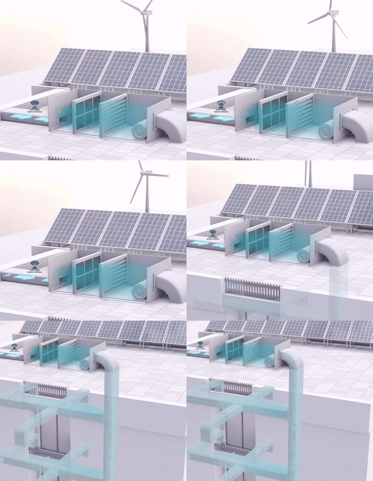
In a data centre, cooling is the largest load. Follow the air, step by step, to see how Wall-GapS™ works together with the room's own cooling.
Wall-GapS™ integrated in a data centre (section view)
-
Outside air enters through the façade
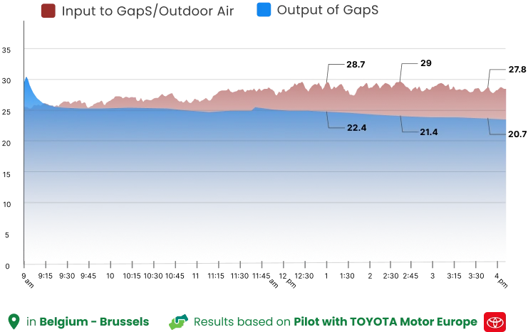
The Wall-GapS™ façade takes in outside air and cleans and cools it on the way in: −5 to −7.6 °C cooler in the Brussels pilot, with up to 50 % of PM2.5 and up to 90 % of PM10 removed. The outdoor temperature was recorded at a maximum of 29 °C.
-
The cooling unit gets a head start
The CRAH (computer room air handler) receives air that is already cooler and cleaner. The chillers behind it work less, and its filters stay clean for longer.
-
Cold air under the raised floor
The CRAH pushes the cold air into the raised floor, which carries it under the room to the server rows.
-
Up through the cold aisles
Perforated floor tiles release the cold air in front of the racks, where the servers take it in.
-
Through the servers
The air passes through the servers, takes up their heat and leaves into the closed hot aisle.
-
Back through the ceiling
The hot air rises into the ceiling and returns to the CRAH. The cycle starts again, with less heat to remove.
Cooling and energy
Cooling energy saving
Measured
−5 to −7.6 °C
in the pilot
Measured Performance & Significant Savings
In the pilot we measured the incoming air 5 to 7.6 °C cooler.
Modelled for 29 cities: 10 % to 49 % less cooling electricity (47 % in Brussels), built on measured pilot data; in projects, savings will be measured against a weather-normalised baseline (IPMVP).
Clean air
Active Lungs of our Cities
Our Wall-GapS units do more than just cooling and insulation; they actively cleaning the air. The specialized filtration process removes pollutants, and the modular design allows for easy vertical extension to enhance purification, with key benefits:
- Reduced HVAC Maintenance: Less pollution reaches your system, reducing blockages.
- Higher System Efficiency: With cleaner filters, fan motors operate at peak efficiency for longer.
- Measured results: in our tests the panels removed up to 50 % of PM2.5 and 90 % of PM10.
Up to
50 %
PM2.5 removed
Up to
90 %
PM10 removed
Insulation
Facade surface 19 °C cooler in direct sun
Buildings are like batteries on a hot day, absorbing heat from the sun and releasing it slowly at night. This heat absorption makes HVAC systems work harder the next day to cool the indoors, using more energy.
Measured on the pilot: 42.2 → 22.9 °C. An effective solution to reduce this heat buildup will result in significant energy savings for the building.
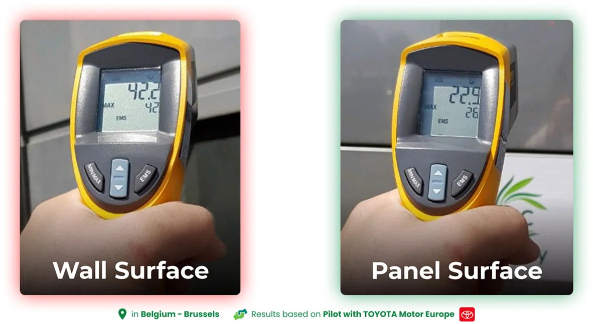
Ref: Results are based on the Pilot implementation in collaboration and inside TOYOTA Motor Europe
Reference case
A 5 MW data centre in Brussels
Calculated for a 5 MW legacy data centre with 1,000 m² of Wall-GapS™, using real data from our Toyota pilot and local weather, energy prices and grid data.
7,695 MWh / year
electricity saved
47 %
less electricity for cooling
€998 k / year
net saving, after water and maintenance
Testimonials

Tests
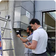
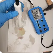
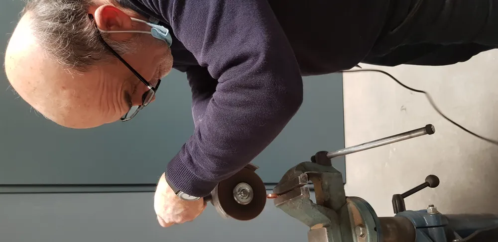
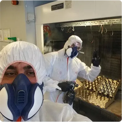
Test & Analyses
At PurCity, we meticulously conduct tests and analyses. Navigating the intricacies of data, we illuminate the path of innovation, ensuring that every step is grounded in thorough research and careful analysis.
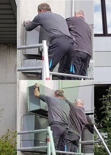
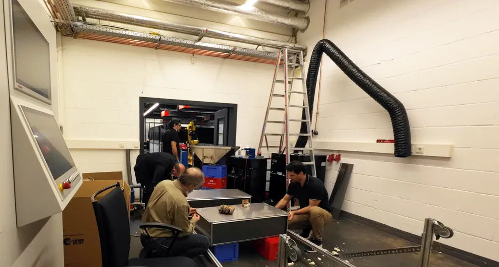


Mounting
Scenarios
Four ways of fixing the panels, depending on the building's wall and structure.
-
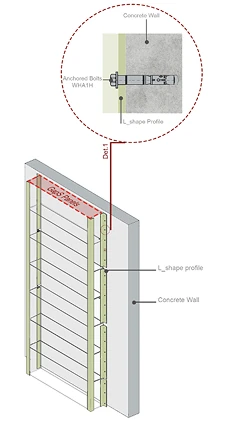
Scenario 1
Concrete Wall (Flat Surfaces/Walls)
On a flat concrete wall: L-shaped profiles are anchored to the wall with bolts, and the GapS panels are fixed between them.
-
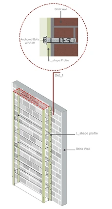
Scenario 2
Brick Wall (Flat Surfaces/Walls)
The same fixing on a flat brick wall: L-shaped profiles anchored into the brickwork carry the panels.
-
Scenario 3
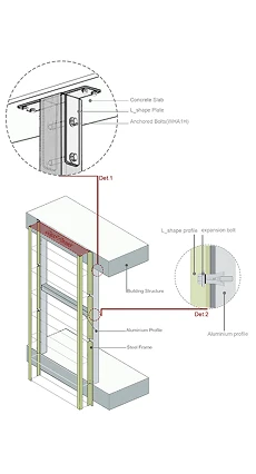
Double Façade (Concrete Floor)
As a second skin in front of the building: a steel frame with aluminium profiles carries the panels and is fixed to the edge of each concrete floor with L-shaped plates and anchored bolts.
-
Scenario 4
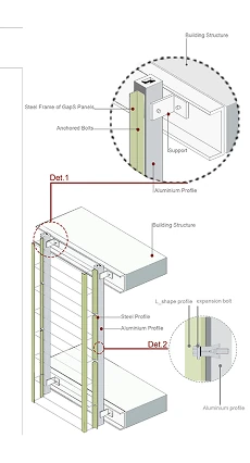
Double Façade (Metal Beam Floor)
The same second skin on a steel structure: the steel frame of the GapS panels is fixed to the metal floor beams with supports and anchored bolts.
Structure
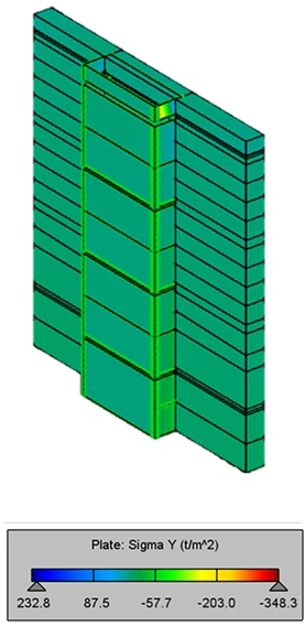
Stress analyses
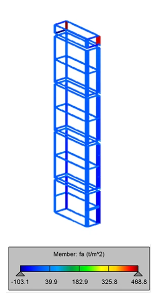
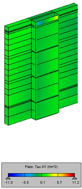
The panels and their fixing were analysed in a structural model. The colours show the stress in each part, in tonnes per square metre (the scale is under each picture).
-
Analysis 1
Axial stress analyses
The stress along each member of the panels' steel frame.
-
Analysis 2
Shear stress on Steel plates & concrete wall
The shear (sliding) stress in the steel plates and the concrete wall.
-
Analysis 3
Tension and compression stress
Where the plates are pulled (tension) and where they are pressed (compression).
Safety
Fire Safety
We follow local regulations and these standards: panel core of mineral wool (A2-s1,d0) or PIR (B-s1,d0) to EN 13501-1; large-scale facade fire test to BS 8414 / ISO 13785-2.
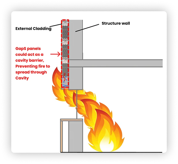
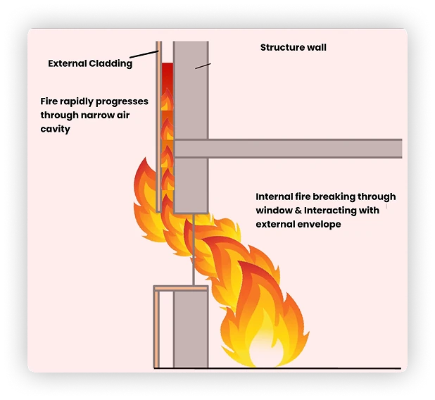
By design, the water-filled panels can act as a cavity barrier that helps stop fire spreading through the cavity.
-
With
-
Without
Join the Change
Discover how our technology and services can deliver significant impact and sustainability to you!
 AI Assistant
